English
 Русский
 Español
 Français
 Português
 العربية
About Us
- Company
- Customers
- Technical Highlights
- Advantages
- Company History
- Environmentally-friendly Facility
- Patents
- Quality Control
- R&D
- Mucking Loader Manual
- Mucking Loader Technical Description
- Mucking Loader Operation Description
- Mucking Loader Maintenance
- Mucking Loader Operation Notes
- Roadheader Manual
- Roadheader Technical Description
- Roadeheader Maintenance
- Roadheader Notes
- Roadheader Operating Method
- Mine Shuttle Car Manual
- Mine Shuttle Car Maintenance
- Mine Shuttle Car Operation
- Mine Shuttle Car Technical Description
- Mine Shuttle Car Notes
- Trolley Locomotive Maintenance
- Maintenance Manual of Drilling Jumbo
- Contact Us
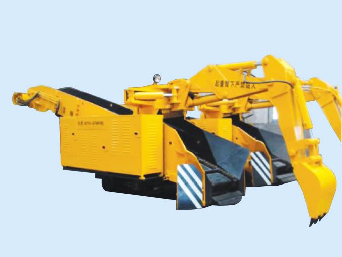
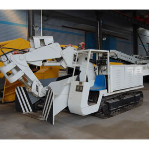
Roadheader Technical Description
A. Hydraulic System
Brief introduction: All the EBH45 roadheader machines are driven by hydraulic system, which is directly powered by a 75 kW electric motor. This motor can directly drive two variable displacement pumps:
(1) The two variable displacement pumps separately supply oil to two oil hydraulic circuits.
(2) The front pump is a load-sensing variable displacement piston pump. It controls the traveling of the machine and the working of cylinder through pilot valve.
(3) The rear pump is a variable displacement piston pump that controls the rotation of the cutting head.
1. Functions of the Hydraulic System
The hydraulic system controls:
(1) Traveling of the roadheader machine.
(2) Rotation of the cutting head.
(3) Rotation of the star wheel.
(4) Actuation of the transporting mechanism.
(5) Front and back, up and down, as well as left and right movement of the cutting head.
(6) Ascending and descending of the shovel plate.
(7) Ascending and descending of the back prop device.
2. Oil Pump and Hydraulic Motor
The pumping station is driven by 75kW electrical motor. Through the combination of variable displacement oil pump and pilot valve, the pressure is separately sent to the cutting, loading, transporting and traveling mechanisms as well as the hydraulic motor and oil cylinder of the back prop device. The roadheader has nine cylinders in total: 3 working cylinders for the cutting arm, 2 hoisting cylinders, 2 angling cylinders for the cutting arm and 2 hoisting cylinders for the back prop device.
3. Console
(1) The console is mounted with operating stick, pressure gauge, oil temperature gauge, and water thermometer.
(2) The movement of all the oil cylinders and hydraulic motors is controlled by operating the sticks.
(3) Pressure and temperature of all oil circuits can be detected by the pressure gauge and thermometer.
4. Load and Transport Circuit
(1) The star wheel motor (load and transport circuit) is driven by variable displacement piston pump, and its hydraulic motor is controlled by the oil from the pump (pump pressure: 20MPa).
(2) The conveyor motor is driven by constant power variable displacement piston pump, and its hydraulic motor is controlled by the oil from the pump (pump pressure: 25MPa).
(3) The reversing valve of the load and transport mechanism is mounted under the console. The clockwise and anticlockwise rotation of the load and transport mechanism is controlled by the operating stick.
5. Traveling Circuit
(1) The traveling circuit is driven by variable displacement piston pump, and both of the hydraulic motors which separately control the left and right traveling are controlled by the pressure oil from the pump (pressure: 31.5MPa).
(2) The reversing valve of the hydraulic motor is integrated on the pilot multi-tandem valve.
6. Pilot Circuit
(1) All the machine operations are controlled by pilot valves.
(2) There are 13 pilot-operated valves in total.
(3) The pilot oil supply assemblies include the pilot oil source valve, pilot filter and pilot safety valve.
(4) Pressure: 3.5MPa.
7. Hydraulic Cylinder Circuit
(1) The hydraulic cylinder circuit is driven by load-sensing variable displacement piston pump.
(2) The oil from the pump separately controls the rotation, three oil cylinders of the cutting arm, the oil cylinder of the shovel plate and the back prop.
(3) Set the rotation pressure at 29.5MPa and the pressure of oil cylinder at 27MPa.
(4) The hydraulic support circuit is designed with a hydraulic lock.
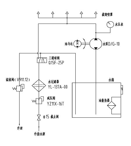
B. Spray Cooling System
The principle of the spray cooling system is shown as follows:
Brief introduction: All the EBH45 roadheader machines are driven by hydraulic system, which is directly powered by a 75 kW electric motor. This motor can directly drive two variable displacement pumps:
(1) The two variable displacement pumps separately supply oil to two oil hydraulic circuits.
(2) The front pump is a load-sensing variable displacement piston pump. It controls the traveling of the machine and the working of cylinder through pilot valve.
(3) The rear pump is a variable displacement piston pump that controls the rotation of the cutting head.
1. Functions of the Hydraulic System
The hydraulic system controls:
(1) Traveling of the roadheader machine.
(2) Rotation of the cutting head.
(3) Rotation of the star wheel.
(4) Actuation of the transporting mechanism.
(5) Front and back, up and down, as well as left and right movement of the cutting head.
(6) Ascending and descending of the shovel plate.
(7) Ascending and descending of the back prop device.
2. Oil Pump and Hydraulic Motor
The pumping station is driven by 75kW electrical motor. Through the combination of variable displacement oil pump and pilot valve, the pressure is separately sent to the cutting, loading, transporting and traveling mechanisms as well as the hydraulic motor and oil cylinder of the back prop device. The roadheader has nine cylinders in total: 3 working cylinders for the cutting arm, 2 hoisting cylinders, 2 angling cylinders for the cutting arm and 2 hoisting cylinders for the back prop device.
3. Console
(1) The console is mounted with operating stick, pressure gauge, oil temperature gauge, and water thermometer.
(2) The movement of all the oil cylinders and hydraulic motors is controlled by operating the sticks.
(3) Pressure and temperature of all oil circuits can be detected by the pressure gauge and thermometer.
4. Load and Transport Circuit
(1) The star wheel motor (load and transport circuit) is driven by variable displacement piston pump, and its hydraulic motor is controlled by the oil from the pump (pump pressure: 20MPa).
(2) The conveyor motor is driven by constant power variable displacement piston pump, and its hydraulic motor is controlled by the oil from the pump (pump pressure: 25MPa).
(3) The reversing valve of the load and transport mechanism is mounted under the console. The clockwise and anticlockwise rotation of the load and transport mechanism is controlled by the operating stick.
5. Traveling Circuit
(1) The traveling circuit is driven by variable displacement piston pump, and both of the hydraulic motors which separately control the left and right traveling are controlled by the pressure oil from the pump (pressure: 31.5MPa).
(2) The reversing valve of the hydraulic motor is integrated on the pilot multi-tandem valve.
6. Pilot Circuit
(1) All the machine operations are controlled by pilot valves.
(2) There are 13 pilot-operated valves in total.
(3) The pilot oil supply assemblies include the pilot oil source valve, pilot filter and pilot safety valve.
(4) Pressure: 3.5MPa.
7. Hydraulic Cylinder Circuit
(1) The hydraulic cylinder circuit is driven by load-sensing variable displacement piston pump.
(2) The oil from the pump separately controls the rotation, three oil cylinders of the cutting arm, the oil cylinder of the shovel plate and the back prop.
(3) Set the rotation pressure at 29.5MPa and the pressure of oil cylinder at 27MPa.
(4) The hydraulic support circuit is designed with a hydraulic lock.
B. Spray Cooling System
The principle of the spray cooling system is shown as follows:
Related Products