English
 Русский
 Español
 Français
 Português
 العربية
About Us
- Company
- Customers
- Technical Highlights
- Advantages
- Company History
- Environmentally-friendly Facility
- Patents
- Quality Control
- R&D
- Mucking Loader Manual
- Mucking Loader Technical Description
- Mucking Loader Operation Description
- Mucking Loader Maintenance
- Mucking Loader Operation Notes
- Roadheader Manual
- Roadheader Technical Description
- Roadeheader Maintenance
- Roadheader Notes
- Roadheader Operating Method
- Mine Shuttle Car Manual
- Mine Shuttle Car Maintenance
- Mine Shuttle Car Operation
- Mine Shuttle Car Technical Description
- Mine Shuttle Car Notes
- Trolley Locomotive Maintenance
- Maintenance Manual of Drilling Jumbo
- Contact Us
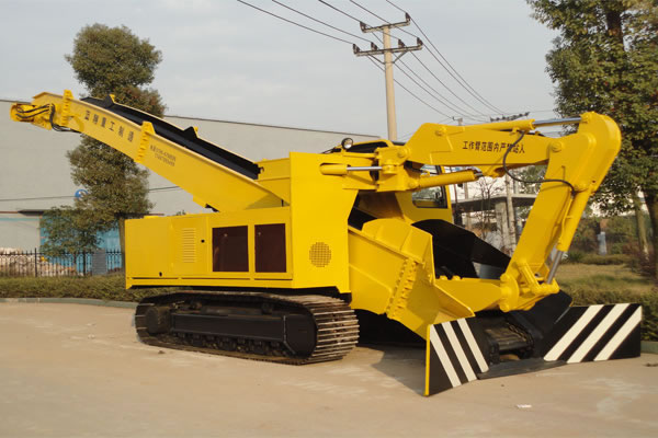
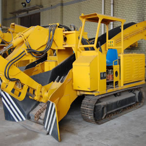
Mine Shuttle Car Technical Description
Mine Shuttle Car Technical Description
A. Bogie (Mine Shuttle Car Chassis)
Brief introduction
(1) The chassis of the bogie is the latest sphere-structured and low gravity center one which can automatically adjust the balance of the mine shuttle car.
(2) Each bogie has four wheels and the wheels can land steadily on the steel rail and move quite flexible.
(3) Each bogie can turn 360°.
Parts
1. Central Spindle
(1) Definition: Central spindle is mounted on the middle of the bottom beam of the bogie. It holds the impact force of the whole mine shuttle car.
(2) The outdated central spindle and its disadvantages
Some factories still use the outdated first generation central spindle. In the old method the connection is done by a 50mm hole in the middle of the central spindle and a bolt. When the shuttle car starts running, the bolt and the central spindle will wobble all the time and abrasion is especially easy to happen. After a period of abrasion a large gap will appear. This increases the likelihood of getting of track. This is dangerous and it makes the maintenance strenuous.
(3) The newest central spindle and its advantages: we use the latest third generation S20 mine shuttle car. (Patent No.: ZL2008 2 0113046.4).
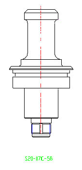
According to the response of Yunnan Copper Group, our long-term cooperative partner, the mine shuttle car produced by us has served for three years at its working site and it has never broken for even once.
2. Wheel: it’s made of manganese alloy steel for increased friction durability.
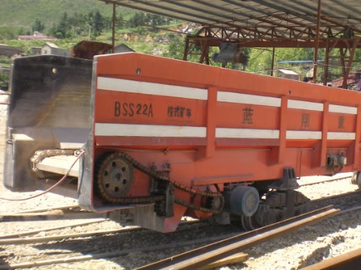
B. Parts of Transport Trough
1. Some factories weld the wear-resistant bottom plate without any abrasion reduction protection. By this, the bottom plate will deform only after 3-5 months, and the friction coefficient will rise afterward. A series of destructive problems will follow.
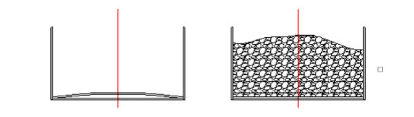
Unloading Loading
2. Our bottom plate welding method and its advantages
(1) Our company improves the design by curving the bottom plate with a little radian (see the above picture).
(2) With this little curve, the scraper might have to overcome the gradient when the shuttle car is empty. But as it’s empty, a little load caused by the gradient will not affect the shuttle car’s whole performance.
(3) While if the car is full-loaded, the curve will become a straight line. In this case the scraper transports and discharges horizontally, so the load reaches minimum level and then the whole transmission mechanism will be protected.
3. The parts produced by us are 40%-60% more wear-resistant compared with our competitors’ parts.
4. Our parts can rebound to the original shape after unloading thanks to the flexibility.
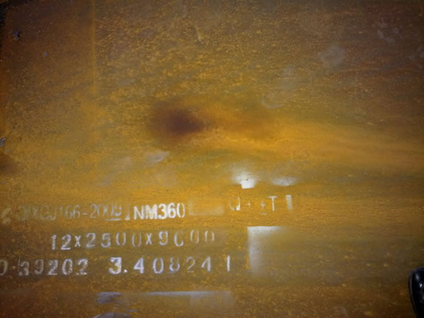
5. We use NM360 high-strength steel plat, with its service life five times longer than 16Mn structural steel.
C. Trailing Device
1. The outdated trailing method and its disadvantage
(1) The outdated trailer rod moves the whole shuttle car by pulling the bogie. When turning a corner, the bogie is tugged by force (see the picture below), so its flexibility is restricted and it’s easy to derail.
(2) Another disadvantage of this old trailing method is that it’s easy to get the central spindle crack, because the movement of the whole car is trailed through the bogie, this also means it’s trailed through the central spindle. Moving the shuttle car just by the central spindle is easy to get it break down.
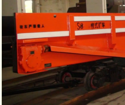
2. Our trailing
method and its advantages
(1) The trailing rod of our shuttle car is directly connected with the car (see the picture below). In this case, the bogie is driven by the body of the shuttle car, so the central spindle will not be prone to get damaged.
(2) The rotation of the bogie is not intervened by the trailing rod, because the rod has to work on the car body. In this way, the bogie can rotate 360°, and it’s less likely to get off the track.
Note
1. Working conditions of electrical apparatus elements
(1) The height above sea level is lower than 1000m.
(2) The surrounding temperature should not be higher than 35℃.
(3) The relative temperature of air is lower than 25℃.
(4) No corrosive gas, steam or dust that may cause damage exists in the surrounding medium.
2. The ground lead core of rubber cable
(1) It should be connected with the ground lead of explosion-proof pin by terminal.
(2) Other usage of it is prohibited.
3. All the device that needs to be grounded, including the track and cables’ lead core, should be grounded.
4. The pin has four pairs of core wires, three are main electrical power cores and one is ground lead. Don’t just connect the main power without grounding the ground lead.
5. Cover the pin assembly with safety cap after unplug.
6. When using the pin, connect the pin with the outlet of the magnetic starter and the pin base with the electrical motor outlet. Wrong connections are prohibited.
7. The electrical appliance’s maps and elements of SD-25/6B, SD-25/9B, SD-30/6B, SD-30/9B, SD-35/6B, SDB35/9B and SD-20/Bare are the same. The only difference is that the electric motor of SD-30/6B, SD-30/9B, SD-35/6B and SD-35/9B are 30kW.
A. Bogie (Mine Shuttle Car Chassis)
Brief introduction
(1) The chassis of the bogie is the latest sphere-structured and low gravity center one which can automatically adjust the balance of the mine shuttle car.
(2) Each bogie has four wheels and the wheels can land steadily on the steel rail and move quite flexible.
(3) Each bogie can turn 360°.
Parts
1. Central Spindle
(1) Definition: Central spindle is mounted on the middle of the bottom beam of the bogie. It holds the impact force of the whole mine shuttle car.
(2) The outdated central spindle and its disadvantages
Some factories still use the outdated first generation central spindle. In the old method the connection is done by a 50mm hole in the middle of the central spindle and a bolt. When the shuttle car starts running, the bolt and the central spindle will wobble all the time and abrasion is especially easy to happen. After a period of abrasion a large gap will appear. This increases the likelihood of getting of track. This is dangerous and it makes the maintenance strenuous.
(3) The newest central spindle and its advantages: we use the latest third generation S20 mine shuttle car. (Patent No.: ZL2008 2 0113046.4).
According to the response of Yunnan Copper Group, our long-term cooperative partner, the mine shuttle car produced by us has served for three years at its working site and it has never broken for even once.
2. Wheel: it’s made of manganese alloy steel for increased friction durability.
B. Parts of Transport Trough
1. Some factories weld the wear-resistant bottom plate without any abrasion reduction protection. By this, the bottom plate will deform only after 3-5 months, and the friction coefficient will rise afterward. A series of destructive problems will follow.
2. Our bottom plate welding method and its advantages
(1) Our company improves the design by curving the bottom plate with a little radian (see the above picture).
(2) With this little curve, the scraper might have to overcome the gradient when the shuttle car is empty. But as it’s empty, a little load caused by the gradient will not affect the shuttle car’s whole performance.
(3) While if the car is full-loaded, the curve will become a straight line. In this case the scraper transports and discharges horizontally, so the load reaches minimum level and then the whole transmission mechanism will be protected.
3. The parts produced by us are 40%-60% more wear-resistant compared with our competitors’ parts.
4. Our parts can rebound to the original shape after unloading thanks to the flexibility.
5. We use NM360 high-strength steel plat, with its service life five times longer than 16Mn structural steel.
1. The outdated trailing method and its disadvantage
(1) The outdated trailer rod moves the whole shuttle car by pulling the bogie. When turning a corner, the bogie is tugged by force (see the picture below), so its flexibility is restricted and it’s easy to derail.
(2) Another disadvantage of this old trailing method is that it’s easy to get the central spindle crack, because the movement of the whole car is trailed through the bogie, this also means it’s trailed through the central spindle. Moving the shuttle car just by the central spindle is easy to get it break down.
(1) The trailing rod of our shuttle car is directly connected with the car (see the picture below). In this case, the bogie is driven by the body of the shuttle car, so the central spindle will not be prone to get damaged.
(2) The rotation of the bogie is not intervened by the trailing rod, because the rod has to work on the car body. In this way, the bogie can rotate 360°, and it’s less likely to get off the track.
1. Working conditions of electrical apparatus elements
(1) The height above sea level is lower than 1000m.
(2) The surrounding temperature should not be higher than 35℃.
(3) The relative temperature of air is lower than 25℃.
(4) No corrosive gas, steam or dust that may cause damage exists in the surrounding medium.
2. The ground lead core of rubber cable
(1) It should be connected with the ground lead of explosion-proof pin by terminal.
(2) Other usage of it is prohibited.
3. All the device that needs to be grounded, including the track and cables’ lead core, should be grounded.
4. The pin has four pairs of core wires, three are main electrical power cores and one is ground lead. Don’t just connect the main power without grounding the ground lead.
5. Cover the pin assembly with safety cap after unplug.
6. When using the pin, connect the pin with the outlet of the magnetic starter and the pin base with the electrical motor outlet. Wrong connections are prohibited.
7. The electrical appliance’s maps and elements of SD-25/6B, SD-25/9B, SD-30/6B, SD-30/9B, SD-35/6B, SDB35/9B and SD-20/Bare are the same. The only difference is that the electric motor of SD-30/6B, SD-30/9B, SD-35/6B and SD-35/9B are 30kW.
Related Products